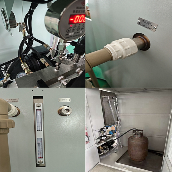
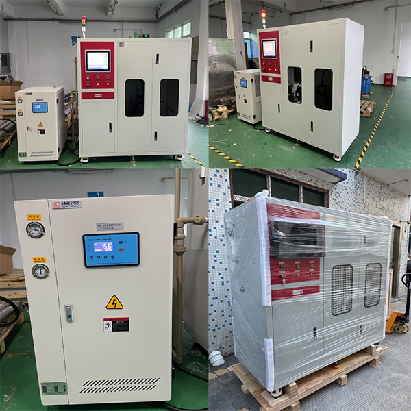
LPG Gas Cylinder Fatigue Test Machine
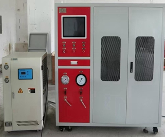
Typical applications:
a) Seamless steel cylinder, CNG cylinder, fire extinguisher pressure cycling fatigue test
b) Pulse pressure cyclic fatigue test for hoses and steel pipes
c) Pressure cycling fatigue test for pressure resistant shells and valves
4. Technical parameters
a) Applicable medium: water;
b) Maximum pressure output range: 3.2MPa;
c) Pulse frequency: ≤ 15 times/minute, adjustable;
d) Gas cylinder capacity: 1~35L;
e) Simultaneously test the pipeline: 3 channels;
f) Pressure detection accuracy: ≤± 0.5% F.S;
g) Pressure control accuracy: ≤± 1.0% F.S;
h) Timing range: 0-9999H;
i) Power requirement: AC380V 50Hz 5kw;
j) Equipment usage: Suitable for indoor working conditions
5. System features
Adopting two-stage turbocharging, modular design, proportional pressure regulation, and closed-loop control.
(1) Allow gas cylinders to be separated by volume and workstation
Namely: 0-8KG (tentative) gas cylinder → 3 workstations
15KG (tentative) gas cylinder → 3 workstations
(2) Pulse frequency: allows customers to allocate
(3) The experimental device is equipped with a regular pressure gauge with an accuracy of not less than 1.6 and a range of 5MPa, as well as a precision pressure gauge with an accuracy of not less than 0.4 for calibration purposes
(4) The experimental software real-time draws the pressure cycle P-T curve, and the experimental waveform is basically the same as an approximate trapezoidal wave, with a platform corresponding to the upper and lower holding times; The upper and lower limits of the test pressure can be freely set and meet the requirements of the test standards; The computer automatically generates pressure time curves, stores the data, and prints test reports at any time.
(5) The testing software is mature and stable, with a user-friendly interface that is easy to operate.
(6) After clicking start, the system automatically records the number of cycles; Stop counting after stopping.
(7) Record the number of cycles, upper and lower limits of pressure, pressure testing temperature, and other test data.
System safety:
(1) The components used in system design have reserved safety factors, and the system is set with the highest safety protection pressure. The system overpressure safety valve will automatically trip to relieve pressure. And the system is equipped with a cooling system to ensure a relatively constant test temperature;
(2) The monitoring software is set with safety pressure monitoring, overpressure, system automatic feedback alarm, and automatic pressure relief. When the gas cylinder leaks, it can delay the alarm and automatically shut down;
(3) The monitoring system of the system is separated from the high-pressure components, and our company provides professional explosion-proof construction drawings for the workpiece installation site to ensure safe use;
Typical System Principle Diagram:
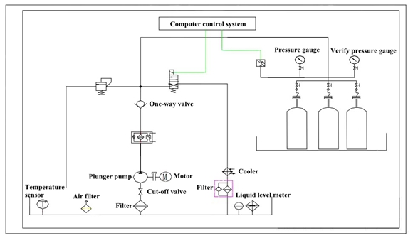
The equipment consists of a pump valve installation cabinet, a microcomputer control system, a control cabinet, and an electrical box. The installation of equipment pipelines follows the principle of horizontal and vertical alignment, with a reasonable layout and separation of oil and electricity. The high-pressure testing pipelines are connected by stainless steel pipes, which are beautiful and durable. The control cabinet is the core part of the equipment, and the top layer adopts a single-chip microcontroller full closed-loop control system to achieve full closed-loop control of the entire system. The key components in the middle include solenoid valves, pressure gauges, pressure sensors, etc. The lowest level is the pressure system, which consists of a high-pressure booster pump, valves, and pipelines. It mainly completes the total pressurization of the system (the upper and lower levels of the control system are composed of a microcomputer and a single-chip pressure control unit). The upper computer mainly completes graphic processing, data processing, and data management. The lower computer controls the oil pressure system to achieve the target pressure according to the instructions of the upper computer at the pressure rate.
Working principle:
1.Exhaust: Start the electric motor, the oil pump starts working, pressurize the gas cylinder, and exhaust the air in the pipeline and test gas cylinder.
2.Test pressure setting: Adjust the safety relief valve to set the test pressure.
3.Generation of Pulse Pressure: Apply an electrical signal to the solenoid valve, pressurize the test gas cylinder, and maintain a constant pressure when the maximum test pressure is reached; When the constant pressure time is reached, an electrical signal is given to the solenoid valve, causing the pressure to decrease; Repeat this process repeatedly to generate pulse pressure.
4.Pressure relief: After reaching the number of pressure cycles, stop the electromagnetic valve electrical signal, relieve pressure, and automatically stop the machine.
System composition
1. Main accessories
2. Technical parameters of main accessories:
Hydraulic station:
Install pump valves and accumulators, etc. Provide a pressure output of (0.6-4) MPa, a 300L large liquid tank provides sufficient water for the system and reduces the heating rate, and a water cooler is configured.
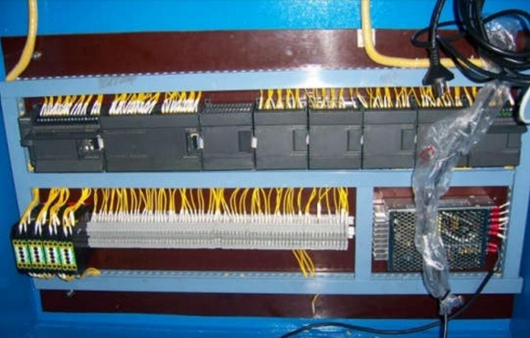
Siemens Programmable Logic Controller and Expansion Module:
The S7-200 CN series PLC is suitable for automation of detection, monitoring, and control in various industries and occasions. The powerful features of the S7-200 CN series enable it to achieve complex control functions whether operating independently or connected into a network. Therefore, the S7-200 CN series has a very high performance/price ratio.
The free communication port method is a distinctive feature of the S7-200 CN PLC. It enables the S7-200 CN PLC to communicate with any other device or controller that has a publicly available communication protocol, meaning that the S7-200 CN PLC can have its own communication protocol defined by the user (such as ASCII protocol).
Any peripheral device with a serial interface, such as a printer or barcode reader, frequency converter, modem, upper PC, etc.
S7-200 CN series micro PLC, used for simple data exchange between two CPUs. Users can program communication protocols to exchange data (such as ASCII characters), and devices with RS232 interfaces can also be connected using PC/PPI cables for free communication.
Analog Expansion Module - The Analog Expansion Module provides the following advantages of analog input/output functionality:
Best adaptability, suitable for complex control scenarios.
Directly connected to sensors and actuators, with a 12 bit resolution and multiple input/output ranges, it can be directly connected to sensors and actuators without the need for external amplifiers.
Flexibility: When practical applications change, PLC can be expanded accordingly and user programs can be easily adjusted.
Install the module card on the standard guide rail and attach it to the guide rail next to the CPU on the right side, and connect it to the CPU through a bus connection cable.
Product Features:
1. The parameters such as output pressure, boosting time, holding time, cycle frequency, and number of cycles during the experimental process can be freely set within the allowable range
2. High pressure and high flow electric booster pump for rapid and stable pressure increase, and adjustable according to different test workpieces
3. The test software displays real-time values of test time, test pressure, and test completion times, automatically saves test results, and alerts for faults and abnormalities. It is suitable for unmanned situations
4. Automatically generate pressure and time curves, display them in real-time, store various data, and print out inspection reports in both Chinese and English at any time
5. The system adopts a solderless connection, conical sealing, can be disassembled repeatedly, is safe and reliable, and is suitable for the sealing requirements of the vast majority of hydraulic systems.
The gas cylinder fatigue testing machine is suitable for fatigue strength testing and life simulation testing of pressure vessels such as liquefied gas cylinders (LPG Cylinders), hydrogen cylinders, and composite gas cylinders. It judges whether the test products meet the requirements according to relevant standards. The gas cylinder fatigue testing machine's parameters such as output pressure, boosting time, holding time, cycle frequency, and number of cycles during the testing process, which can be freely set within the allowable range. The experimental software displays real-time values such as test time, test pressure, and test completion times, automatically maintains the test results, and has an alarm reminder function in case of faults and abnormal states.
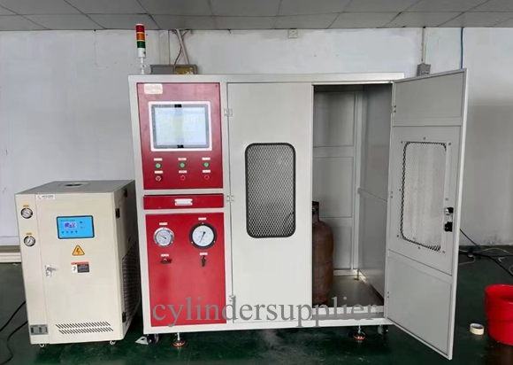
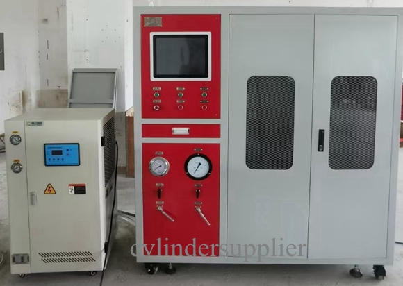
Product Image for Reference:
1. Pressure range: 0 to 100MPa (choose pressure as needed)
2. Test medium: water/oil
3. Testing stations: 2 (expandable)
4. Test frequency: 5-10 times/minute
5. Pressure measurement accuracy: ± 0.5% FS
6. Pressure control accuracy: ± 1% Fs
7. Power supply voltage: AC380V/50Hz (electric pump)
8. Cycle times: 200000 times (adjustable)
