


CNG Compressed Natrual Gas Cylinder Test Line
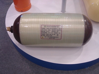
This test line suitable for compressed natural gas (CNG) cylinders with nominal working pressure ≤ 25MPa and nominal volume of (30L-140L), and can also meet the regular inspection of corresponding (CNG) steel lined circumferential wound composite cylinders.
Suitable for the specifications of CNG cylinder:
Cylinder outer diameter: 200-426 mm
Cylinder length: 680-2000 mm
Cylinder weight: no more than 250kg
Composite CNG cylinder no need shot blasting,painting,marking
List of main equipments,tools and accessoires:
1.Automatic feeding machine
2.Nitrogen replacement device
3.Horizontal type valve demounting machine
4.Cylinder internal cleaning machine
5.Reversing machine
6.Hydraulic testing machine with external measuring
7.Automatic water pouring machine
8.Cylinder internal dryer
9.Horizontal type valve mounting machine
10.Air tightness test machine
11.Back bleed control valve station
12.Valve calibration machine
13.Exhaust vacuum bus bar machine
14.Automatic load-down machine
15.Conveyor line
16.Steering wheel
17.Special measurement kits
18.Thread kits
19.Portable combustible gas alarmer with detector
20.Low pressure compressor
21.High pressure air compressor
22.Cylinder bundle
23.Lifting equipment
24.High level water tank
25.Standard cylinder
26.High pressure stainless steel pipe 40 meters
27.Residual gas drainage galvanized pipe 40 meters
28.Low pressure PU hose 12mm dia
29.Quick adapter
30.Water pipe
31.Anchor bolt
32.Dust pipe 20 meters
33.Power distribution cabinet
34.Integrated circuit breaker 5pcs
35.Vessel
36.Control box
37.Pressure creater/transfer
38.Borescope for metal casting
39.Auxiliary tools
40.Other equipments


Overall process and equipment parameters
I.Process flow of inspection line:
Cylinder registration → inspection line on cylinder → nitrogen replacement → cylinder unloading valve → internal cleaning → rust removal on outer surface of cylinder with plug → plug removal (cylinder) → appearance inspection → wall thickness measurement → sound inspection → screw thread inspection of cylinder mouth → internal inspection → nondestructive testing (cylinder) → empty cylinder weighing, data automatically transmitted to industrial control computer → water injection, screw on special joint → full cylinder weighing, data transmission Automatic transmission to the industrial computer → tightening the water jacket cover → loosening the bottle body → lifting the cylinder into the water jacket → automatic compression of the sealed water jacket cover → hydraulic test (computer control) → loosening the water jacket cover → lifting the cylinder out of the water jacket → screwing the water jacket cover → turning over and pouring water → drying → bottling valve → air tightness test → rolling to the exhaust and nitrogen charging area → connecting the bus bar to discharge, pressure relief and nitrogen charging → moving the cylinder to the inspected area cylinder stacking area.
II.Process description:
1. Registration of incoming cylinder → detection line on cylinder → nitrogen replacement
1) After pre registration, the cylinder is turned over to the conveying rack through the bottle loading machine and placed horizontally in the nitrogen replacement station;
2) Manually connect the high-pressure hose connector with the cylinder valve, open the cylinder valve, the display pressure is less than or equal to 0.1MPa, open the exhaust ball valve to exhaust to normal pressure, and close the ball valve; (> 0.1MPa), send the cylinder to the residual gas treatment station for treatment;
3) Open the vacuum pipe ball valve, vacuum the inside of the cylinder and close the ball valve;
4) Open the ball valve of nitrogen pipe, fill nitrogen into the bottle and close the ball valve.
5) Open the exhaust ball valve again, exhaust to normal pressure, remove the high pressure hose, and complete the nitrogen replacement.
6) Since the conveying frame has a certain inclination angle (the angle is 5 °), the cylinder can easily roll to the front of the valve demounting machine.
1.Demounting valve
1) Manually make the cylinder enter the valve demounting machine station;
2) Manually put on the clamping head (the clamping head can be adjusted according to the specification of the gas cylinder), open the manual pneumatic valve of the clamping system, and clamp the gas cylinder;
3) Open the valve unloading button, the chuck rotates to unload the cylinder valve, close the valve unloading button, close the manual pneumatic valve of the clamping system, and the clamping system releases the cylinder;
4) Open the manual pneumatic valve of the bottle puller, pull the cylinder out of the valve demounting machine station, close the manual pneumatic valve of the bottle puller, reset the bottle puller and complete demounting valve.
2.Internal cleaning
1)Manually release 4 gas cylinders into the internal cleaning machine station and automatically locate them;
2)Start the internal cleaning machine and turn over the manual pneumatic valve to make the cylinder mouth turn down by 75 degrees. The turning angle should ensure that there is no residual water in the cylinder.
3)The cleaning machine inside the cylinder is washed with clean water and hot water respectively.
3.Remove the rust on the outer surface of the cylinder with plug → remove the plug
1)The cylinder is rolled to the place where the plug is added, and the collar plug is manually screwed on to protect the thread of the cylinder. Roll the cylinder into the derusting room (the cylinder without external derusting is rotated 90 ° counterclockwise through the steering wheel to enter the sliding guide device and directly roll to the sound inspection place)
2)The cylinder rolls to the working position, and the cylinder pusher pushes the cylinder into the derusting machine. The derusting process can be completed automatically, and shot blasting and recovery can be carried out automatically. Ensure that the cylinder body is not damaged, and the dust is treated by special device to ensure that it meets the requirements of environmental protection.
3)The cylinder will slide out automatically after derusting, and the cylinder will be pulled out of the working position after derusting;
4)Roll the cylinder out of the derusting room and remove the plug manually.
5)If the camera monitoring probe is set in the derusting room, the operator can monitor and control the derusting machine on the control cabinet outside the derusting room.
4.Appearance inspection → wall thickness measurement → sound inspection → cylinder thread inspection → internal inspection
1)The external surface of the cylinder is inspected by hand and the wall thickness of the cylinder is measured by a thickness gauge
2)The cylinder is rolled to the sound inspection station, and the sound inspection is carried out online with a copper hammer.
3)The cylinder rolls to the thread inspection station for inspection.
4)The cylinder is rolled to the internal inspection station, and the internal inspection is carried out by endoscope.
5.Nondestructive inspection → empty cylinder weighing, data automatically transmitted to industrial computer
1)Move the cylinder to the NDT carrier for on-line NDT.
2)The cylinder is sent to the weighing area, the empty cylinder is weighed by the hanging weight device, and the data is transmitted to the hydraulic test industrial computer through communication.
6.Water injection →full cylinder weighing, data automatic transmission→drying → cold air drying
1)Align the water injection pipe with the cylinder mouth, press the water injection control button, and automatically inject high pressure water into the empty cylinder according to the set volume. The water injection is eddy shaped, so as to reduce the bubbles attached to the cylinder body as much as possible. After filling with water, stop the water injection and fill up the surplus manually. Remove the water injection pipe, press the lifting button to lift the cylinder to weigh the full cylinder, and the data is transmitted to the industrial computer through communication.
2)Start the electric hoist to lift the cylinder above the clamping device, lower the cylinder, open the clamping pneumatic valve, the clamping device clamps the cylinder, tighten the water jacket cover, close the clamping pneumatic valve, loosen the cylinder body, start another electric hoist to lift the cylinder above the water tank, and press the down button to lift the cylinder into the water tank.
3)Start the manual pneumatic valve of pressing sealing device to seal the water tank cover automatically.
4)Connect the high-pressure pipe quick connector with the water tank cover, and start the hydraulic test with external measurement method (computer control): water supplement of water tank → water supplement and exhaust of exhaust measuring cup pipeline → pressurization → pressure maintaining → pressure relief → storage of test results.
5)Close the manual pneumatic valve of the compression sealing device and loosen the water tank cover.
6)Press the lifting button, and the electric hoist will lift the cylinder away from the water tank to the position of the clamping device beside the turnover pouring machine.
7)Open the clamping pneumatic valve, clamp cylinder body with the clamping device, and screw the water tank cover.
8)Close the clamping pneumatic valve, loosen the cylinder, and lift it to the tipping machine.
9)Open the inverted water device to turn the gas control valve over, and turn the cylinder mouth down 75 ° and the turning angle shall ensure that no residual water is left in the cylinder.
10)Manually transport the gas cylinder to the dry area, open the manual pneumatic valve of the ejector, and the ejector makes the gas cylinder mouth and the blowing nozzle to be sealed.
11)Press the start button of internal drying, and the electrical control will automatically start the following procedures: open the compressed air valve, pressurize the air intake and drain, and automatically close the compressed air valve when the drain is over; open the internal dryer to dry the inside of the cylinder by electric heating, and automatically open the compressed air valve to dry the inside of the cylinder.
7.Valve mounting
1)Open the manual pneumatic valve and release the cylinder blocker to make the cylinder enter the position of the valve machine.
2)Put on the clamping head manually, open the manual pneumatic valve of the clamping system, and clamp the gas cylinder.
3)Open the valve loading button, rotate the clamping head to tighten the cylinder valve, close the valve unloading button, close the manual pneumatic valve of clamping system, and loosen the cylinder by clamping system.
4)Open the manual pneumatic valve of the cylinder puller, pull the cylinder out of the station of the valve mounting machine, close the manual pneumatic valve of the puller, reset the puller, complete the valve mounting.
8.Air tightness test
1)On the air tightness test station, connect the high-pressure gas hose with the cylinder valve, tighten the seal and open the cylinder valve; connect the high-pressure gas return hose with the cylinder valve to be tested in front of the air tightness test machine, tighten the seal.
2)The operator operates the inflation valve on the console outside the explosion-proof wall, inflates to the gauge pressure of 20MPa, closes the inflation valve, opens the lifting manual control valve, and drops the gas cylinder into the water tank to test whether there is any air leakage. After the test, close the lifting manual control valve and lift the gas cylinder out of the water tank.
3)Open the return valve to let the high-pressure air in the tested cylinder to the cylinder to be tested, and the air pressure in the cylinder is returned to 10Mpa.
4)The operator enter into inside of explosion-proof wall, closes the valve of the tested cylinder, unloads the high-pressure hose, roll the tested cylinder out of the air tightness tester, meanwhile roll the next cylinder onto the air tightness tester.
9.Roll to the exhaust and nitrogen charging area → connect the bus bar to discharge and relieve pressure (residual gas recovery) and nitrogen charging
1)After the air tightness test, roll the cylinder to the exhaust, vacuum and nitrogen filling station, connect the cylinder valve with the high-pressure hose of the vacuum and nitrogen filling manifold, tighten the seal, and open the cylinder valve.
2)Open the exhaust valve to vent the 10MPa residual gas in the cylinder through the manifold (or return to the gas storage tank for recovery).
3)Close the exhaust valve, open the vacuum valve, vacuum the cylinder and close the vacuum valve
4)Open the nitrogen filling valve, flush nitrogen into CNG cylinder, close the valve and remove the high-pressure hose.
10.Surface spraying
1)CNG cylinders connected with a hanging conveying chain through a turnover feeder, and the conveying chain send the cylinder into the automatic spray booth.
2)The automatic spray gun fixed on the elevator which spray the surface of the CNG cylinder, and cylinder rotates automatically when spraying.
3)The painted CNG cylinder transport to the drying channel for drying through the hanging conveyor chain, and then transported to the blanking place.
Equipment Configuration and Main Technical Parameters of Test Line:
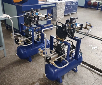
1.Nitrogen Replacement Device
1)Application and characteristics
The national standard GB 19533 "periodic inspection and evaluation of compressed natural gas cylinders for automobiles" stipulates that under the condition of ensuring safety, sanitation and no pollution to the environment, the medium in natural gas cylinders shall be exhausted by appropriate methods, and then replaced by nitrogen. In order to implement the above standard requirements, our company organized scientific and technological personnel to design the device.
The booster device of the device is a nitrogen cylinder, which is directly filled into the natural gas cylinder after decompression. The device has the advantages of simple process, simple investment, reasonable structure, convenient operation, low labor intensity, good effect, safe and reliable operation, and is an ideal type selection equipment for domestic natural gas cylinder detection station
The device adopts two working positions as the basic mechanism.
2)Main technical parameters
a)Model:DQZH-02
b)Nitrogen pressure:6-10MPa
c)Usage pressure:0.4MPa
d)Workstation: 2
e)Combustible gas content after replacement(V):<2%
f)Equipped with pipeline gas pressure reducer
3)Structure
The device is mainly composed of pipeline system, frame and high pressure hose.
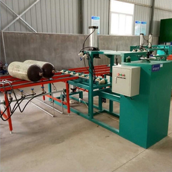
2.Horizontal Type Valve Demounting Machine
1)Characteristics and performance
This equipment is suitable for mounting and demounting of cylinder valves of various specifications with outer diameter of Φ 219 ~ Φ 426 mm and height of L680 ~ 2000 mm of cylinders, it is used in assembly line.
2)Main technical parameters
a)Applicable cylinder specifications:Length ?219×680mm- ?426×2000mm,weight 27-250Kg
b)Typical specification:?325×990mm
c)Motor power:1.5KW
d)Transmission ratio:1:30
e)Maximum speed of spindle:16r/min
f)Productivity:≤3 min/unit
g)Air pressure:0.5~0.6MPa
h)Gross weight:1500㎏
3)Structure and configuration
This machine is composed of frame, pressing device, cylinder turning device, transmission device and electrical control system:
1.Press device: press and release cylinder by the action of pneumatic tool
2.Tipping device: the cylinder can be loaded and unloaded automatically through pneumatic system and tipping mechanism.
3.Transmission device: the motor drives the reducer to make the spindle rotate. The spindle is equipped with universal joint and bottle loading and unloading valve clamp, which can move up, down and back.
4.Electrical control system: control the reverse operation of motor.
Configuration:
1.Frame Set-1
2.Transmission System Set-1
3.Electric control system Set-1
4.Pneumatic pressing and cylinder pushing device Set-1
5.Positioning and turning device Set-1
3.Technical description of cylinder internal cleaning machine
1)Application and characteristics
Cleaning machine is mainly composed of high-pressure cleaning machine, turnover machine and electric control system. It is suitable for cleaning the inside of natural gas cylinder under high pressure to remove the dirt and residue inside the cylinder. Equipped with special cleaning tool, it can clean the inside of cylinder in all directions.
2)Main technical parameters
a)Power consumption: 0.75KW
b)Water consumption flow: 20L/min
c)Cleaning efficiency: 2 min/pcs(80L typical cylinder)
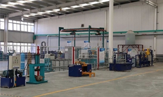
4.Computer controlled external water pressure testing machine
(Hydraulic Barrel Testing Machine)
1)Characteristics and performance
This CNG cylinder hydrostatic test device (hereinafter referred to as the test device) is used to carry out hydrostatic test by external measurement in the process of production, inspection and evaluation of various cylinders. The test device is completely in accordance with GB/T9251-1997" cylinder hydrostatic test method" and American DOT standard.
The control system of the test device is a computer-controlled hydrostatic test system running under Windows 7 /XP operating system. The test device consists of control cabinet, water volume collection and pressurization system, pressure test water tank (jacket), cylinder lifting equipment and weighing electronic scale.
The control software of the test device is LabVIEW. LabVIEW is a real 32-bit / 64 bit compiler, which can generate independent executable files. For example, in the network node computer to complete the cylinder weighing, set the hydraulic test parameters, print the hydraulic test report and view the hydraulic test results.
The designed maximum working pressure of the test device is 64 Mpa, the actual test pressure control accuracy is not less than 10 PSI, and the actual water level measurement accuracy is not less than 0.1g. The test device has a high degree of automation in operation. After inputting the cylinder number of the test cylinder, it only needs to press the key several times from weighing to completing the hydrostatic test under normal conditions.
In the test, the time/pressure, time/water/pressure/water relation curves can be displayed dynamically in graphic mode. The test device saves all the data of the test process, and the user can view all the test data and various test curves of the tested cylinders when necessary. In order to improve the efficiency of hydraulic test,two water tanks (jacket) are set in one set of equipment.
The main functions of the test equipment include:
Parameter setting of cylinder water pressure;
Hydrostatic test of standard CNG cylinder;
Show the test parameters and process of the cylinder that has been hydrostatic tested;
Standard CNG cylinder hydrostatic test report output;
Hydrostatic test;
Cylinder weighing;
Output hydrostatic test report.
2)Main technical parameters
Test pressure: 0-30MPa (adjustable)
Test efficiency: 15~20pcs/h (65L typical cylinder)
Cylinder length: 650—2000mm
Working air pressure: 0.7Mpa
Working air flow: ≥1m3/min
Power voltage: 220V
Control adoption: Computer + data acquisition card + measurement and control software
software program: Self development based on LabVIEW programming environment
3)Structure and configuration:
1.Test machine 1 Set
2.Test control system 1Set computer,display,mouse,keyboard,acquisition card,communication modul,cable,soft ware included
3.Air drive liquid pump 1 Set
4.Pressure sensor 2 Pcs
5.High pressure valve 1 Pcs
6.High pressure needle valve 2 Pcs
7.Solenoid valve 3 Pcs
8.Tank (Water jacket) 2 Sets
9.Tank cover 2 Pcs
10.Cabinet 1 Set
11.Electronic balance 1 Set
12.Hydraulic pipe valve system 1 Set
13.Air control system 1 Set
14.Electronic control system 1 Set
15.Water filtration equipment 1 Set
4)Process of cylinder hydrostatic test system
1.After filling cylinder with water (ensure that all test water is clean), connect the sealing cap (tank cover) with the cylinder
2.Fill the test water into tank about 1/2 position of tank
3.Use the lifting equipment to lift the test cylinder and put it into the test water tank
4.Open the water tank sealing cover and install the exhaust ball-valve
5.Plug in quick connector of water tank and high pressure hose quick connector
6.Start the hydraulic test control system and select 1 / 2 of the tested water tank
7.Open the inflatable seal hand valve
8.Observe whether the pressure display is normal. If there is residual pressure, click the unloading button first
9.Click the water adding button of measuring cup, inject about 500ml of water, and then stop adding water. If the amount of water is enough, it is not necessary to add water
10.Click the water adding button of the water tank, and close the exhaust ball valve after there is continuous water discharged from the exhaust port on the sealing cover of the water tank
11.Close the water tank and add water button
12.After the water quantity of the control interface is stable, click the test start button to start pressurization
13.In the process of pressurization, real-time observation of pressure, displacement and other test parameters,to see if all are normal
14.After the test results are saved and there is no residual pressure, close the inflatable seal hand valve
15.Remove the quick plug of the inflation and high pressure hose
16.Use the lifting equipment to lift the test cylinder to the water pouring machine and remove the water tank sealing cover
17.Complete test and issue test report
5.Technical description of cylinder internal dryer
It is suitable for the internal dry of various gas cylinders, with four working positions and interlock protection device.
Main technical parameters:
(1)Total power of electric heating tube:13KW
(2)Fan total pressure: 383~381mmH2O
Blowing rate: 1020~1210m3/h
Equipped with motor power:2.2KW
Speed: 2900rpm/min
(3)Set temperature:200℃
(4)Use drying temperature: 80-120℃
(5)Drying efficiency: ≈20-30pcs/h
6.Valve Mounting Machine
1)Characteristics and performance
The horizontal cylinder valve mounting machine for natural gas cylinders is designed and manufactured to meet the needs of cylinder manufacturers and absorb the characteristics of similar products at home and abroad. In order to know the real torque in the process of loading and unloading the bottle valve more accurately, this machine is equipped with a digital display high-precision overload protection device, which has the function of setting the motor current to automatically stop. It not only protects the bottle valve, but also reduces the labor intensity, improves the work efficiency and improves the long-term stability.
This equipment is suitable for mounting and demounting of cylinder valves of various specifications with outer diameter of Φ 219 ~ Φ 426mm and height of L680 ~ 2000mm,It is used in assembly line.
2)Main technical parameters
a)Applicable cylinder specifications:?219×680mm- ?426×2000mm Weight:27-250Kg
b)Typical cylinder size: ?325×990mm
c)Motor power:1.5KW
d)Transmition rate: 1:30
e)Maximum speed of spindle:16r/min
f)Productivity: ≤3min/pcs
g)Air supply: 0.5~0.6MPa
3)Structure and configuration
The machine is composed of frame, pressing device, bottle turning device, transmission device and electrical control system
a)Press device: press and release cylinder by the action of pneumatic tool
b)Tipping device: the cylinder can be loaded and unloaded automatically through pneumatic system and tipping mechanism.
c)Transmission device: the motor drives the reducer to make the spindle rotate. The spindle is equipped with universal joint and bottle loading and unloading valve clamp, which can move up, down and back.
d)Electrical control system: control the reverse operation of motor.
7.Gas tightness tester for natural gas cylinder (residual gas recovery, exhaust manifold)
1)Application and characteristics
a)This machine is suitable for air tightness test of natural gas cylinder with length of 800-2000mm.
b)This machine is easy to operate, safe and flexible to use, low labor intensity and high efficiency
2)Technical parameters
a)Working test pressure: 20MPa
b)Work efficiency: 20~40Pcs/hour
c)Compressed air supply pressure:0.5~0.6MPa
d)Weight: 600㎏
3)Structure
It is composed of water tank, hanging rail and lifting mechanism
8.Technical description of vacuum pump
1)Technical parameters:
1.Pumping rate:15 L/S
2.Limit pressure:≤6×10⁻² Pa
3.Motor power:2.2 Kw
4.Temperature:≤80 ℃
5.Noise:≤80 dB(A)
6.Inlet diameter:Φ40 mm
7.Pump speed: 320 rmp
8.Oil consumption: 2.8 L
9.Dimension: 79×53×54 cm
10.Gross weight: 190 Kg
9.Cylinder conveying system
Conveyor frame 50 meters
Shape and material:
Width: 1100 mm,Height:800 mm
10.Lifting and dropping cylinder equipment
1)Equipment usage
It is used for the function of up and down after test
2)Main technology parameter
a)Load: 200kg
b)Compressed air pressure: 0.5~0.6 Mpa
11.Technical description of high pressure air compressor
Main technical parameters:
1、Cooling model: Air cooling
2、Exhaust volume:1.5 m2/min
3、Discharge pressure:25 MPa
4、Speed: 850 r/min
5、Driver:
Power:30 kw
Voltage: 380 v
12.Technical description of natural gas cylinder valve calibration table
Characteristic:
The test bench is suitable for gas tightness test of natural gas cylinder
二、Technical Parameters
1、Air source pressure ≥20MPa
2、Test pressure:20MPa
3、Test medium:Air
4、Work efficiency:40~50 Pcs/hour
5、Work pressure:0.4~0.5MPa
6、Dimension:660×600×1050mm
13.Technical description of air compressor
14.Technical Parameters:
1)Motor power: 15 KW
2)Exhaust volume: 2m3/min
3)Discharge pressure: 1.0Mpa
4)Rotational speed: 860 r/min
15.Thread gauge, inspection tools and measuring tools
PZ27.8:Taper thread gauge; Taper smooth plug gauge; Taper smooth ring gauge;
Taper thread
16.Portable combustible gas concentration detector
1)Gas type:Combustible gas, hydrogen sulfide, carbon monoxide, etc
2)Test range:Volume ratio 0-100%
3)Measurement accuracy: ±2%
17.Residual gas recovery and exhaust, vacuum and nitrogen filling bar
1)Work station: 10
2)Work efficiency: 20-40pcs/hour
3)Air source pressure: 0.5-0.6Mpa
Equipment usage of environment and safety protection
Equipment usage environment
Working environment temperature:-10℃ ~ +40℃
Working environment humidity:≤85%
Working voltage: 380V~±10%
There is no large amount of dust, flammable and corrosive gas in the work site.
In the above working environment, all kinds of equipment of the inspection line can work normally.
The equipment of the test line is designed and manufactured in strict accordance with the national professional standards, without environmental pollution. All electrical insulation properties pass the strict test before leaving the factory, meeting the relevant standards.
ISO 9001